3D-Printer Injection Molding - 3DPIM
Even a simple filament-based 3D printer can produce parts with high precision and speed with a few tricks. This procedure is almost free.
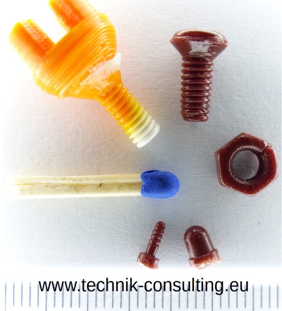
Photo: Dirk Brunner; License: CC BY SA 3.0
Easy process
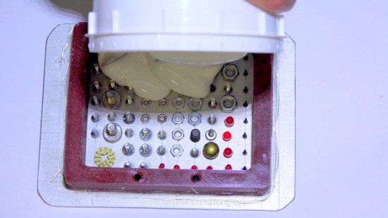
The process is very simple. You have a small object to be copied. A silicon mould is produced from this object, which is then filled with plastic at the 3D printer. With the 3D printer, further object details can then be built directly onto the silicone mold in the usual 3D printing process.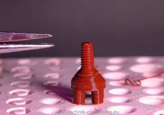
Photo: Dirk Brunner; License: CC BY SA 3.0
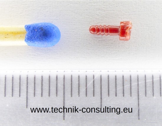
Photo: Dirk Brunner; License: CC BY SA 3.0
Automation possible
The process can be fully automated with a simple 3D printer. For example the 3D printer can pull out the object of the silicone mold or press it out after completing the object. As a result the silicone mold is free again and the next printing process can begin. The demoulded object can be carried into a crate. Only enough filament must be provided. This means that small series production or serial production is no longer a hindrance.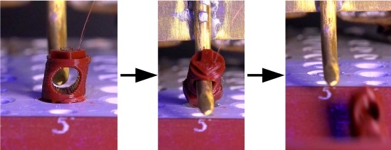
Photo: Dirk Brunner; License: CC BY SA 3.0
In order to be able to try out this new method, a detailed guide follows.
Instructions for the 3D-PIM procedure
Object selection for 3D-PIM
The silicone mold is a negative mold. The object should therefore be suitable with regard to the production of the silicone mold. So that the silicone mold can be well filled by the 3D printer some points have to be considered:No highly absorbent or porous surfaces
These would cause problems in the mold production with the liquid silicone. Alternatively the surface may be sealed with e.g. vaseline, wax or special plasticine. Well-suited are smooth surfaces of e.g. metal, plastic, glass. Unsuitable are for example sponges, textiles, rough wood.
Observe the L / D ratio of the object
This is the ratio of length divided by the diameter. A short screw is easier to fill than a long one. The plastic cools when it is injected into the mold and hardens. As a result, long parts can only be produced conditionally because the lower part is not molded. For initial tests you should try an L / D ratio of a maximum of 2. This means if the object has a diameter of approx. 4 mm, it should be a maximum of 8 mm deep, better less.
Undercut
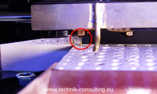
If the object is to be built up after injection, a slight undercut is helpful.

The picture shows the silicone mould orange and the component blue. In the demoulding direction (arrow), the undercut (red circle) obstructs the demoulding. Due to the flexible silicone the component can still be demoulded. It keeps through the undercut better in shape. This allows the component to be printed after the injection in the normal layer process.
Think of the thread in the silicone mold and an individual screw head in the standard 3D printing process. The plastic will not adhere to the silicone mold. If the object has no undercut, it may migrate after or during injection. This is strongly dependent on the object. Flat parts are much more susceptible than deeper ones. For initial tests use for example a short M4 screw.
Silicone material
There are different types of silicones with different properties. The good news are that the 3DPIM process works with almost every silicone. Softer silicone grades have proven themselves, which are also suitable for lead / tin casting. One-component silicone (e.g. silicone in a cartridge for grouting) is unsuitable since the curing takes a very long time. Here you can typically expect one mm per day. A 20 mm thick mold then takes around 10 days (since mm per side counts). Better is the use of two components silicone. Mix the liquid silicone with the catalyst. This mixture subsequently hardens uniformly. Typically such molds can be used after 24 hours.
Preparation of the mold
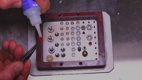
Place the objects to be molded on a smooth surface such as a glass plate. To be sure you can treat the glass plate and the object with mold release agents (e.g. Film release agent PVA).
The hardened silicone can be removed more easily with release agent.
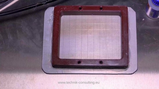
If the objects are not fixed they can move or float during the silicon casting. You need a small box around your objects into which you can pour the silicone. A simple construction of plastic or metal strips is sufficient. Pros print this box with the 3D printer. As a further object they add a needle or a thin nail. This serves later as a reference.
Mix the two components together according to the instructions. If you have a vacuum pump for degassing this is perfect. The mixing cup should have about five times the volume of the silicone otherwise it will rise above the mixing cup edge during degassing.
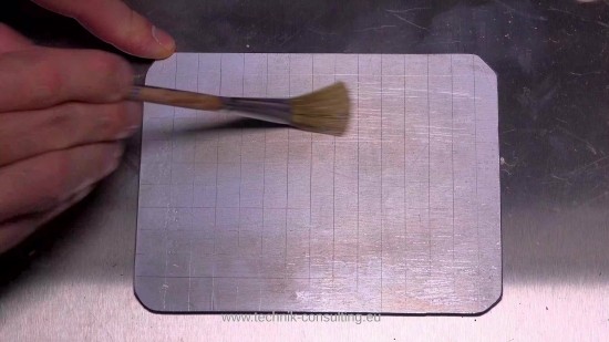
If you do not have a vacuum pump for degassing use the silicone mixture to brush the objects several times. As a result air inclusions on the surface are minimized.
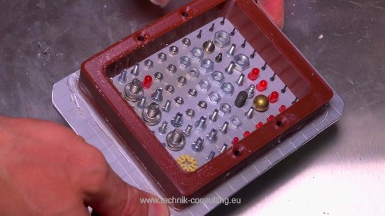
Wait until the silicone polymerization is completed. Then remove the box and the objects. Clean the silicone mold of any release agent residues.
Tempering silicone mold recommended
Tempering is recommended as it improves the material properties of the silicone. Please follow the instructions. Alternatively heat the silicone mold in a water bath very slowly (= several hours!) to about 60 ° C and keep at this temperature for a few hours. If the silicone is heated too fast the mold can soften and become useless. This is dependent on the silicone.
Mounting the silicone mold
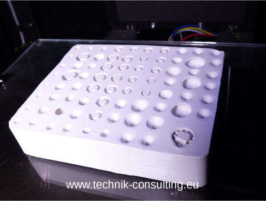
You can glue the silicone mold onto a plate using a primer. This plate is attached to the 3D printer. Alternatively you can use a 3D printed body to mount the silicone mold. It is only important that the silicone mold is securely attached to the print bed.
First test
Almost all 3D printers can be operated manually. Use this for a first test! Heat up the print head and place it over the cavity of your object in the silicone. Lower the printhead as far as it will go. Extrude as much plastic until it swells out of the mold again. Already the first test is ready. Move the printhead aside and wait for the plastic to cool down. Then remove your first object. It is normal if this is not yet perfect. The optimization is done later.
Reference position
You can on the one hand connect the silicone mold firmly to the pressure bed and use the reference position of the 3D printer. On the other hand you can also use this position as a reference by using a short nail in the silicone mold. The nail is removed for safety after the referencing.
In the case of manual referencing the print head has proven to work just right and exactly across the nail. So you have the reference in the plane. The surface of the silicone mold is recommended as a reference in z axis.
The manual reference is particularly suitable for rapid tests or if the silicone mold can not be fixed firmly on the pressure bed.
Programming 3D printer for 3DPIM
For the optimization of the injection a simple test program is recommended so that the most important parameters can be set. These are:- Type of plastic
- Position print head
- Temperature plastic
- Extrusion rate
- Bed temperature
3D printer program sequence for 3DPIM
- Heating up
- Clean the print head (= extrude plastic)
- Positioning over the cavity
- Extrude
- Possibly further geometry printing (e.g. screw head)
- Possibly remove part and jump back to point 3 for next part
Sample program (snippet) 3D printer for 3DPIM
; InitialisingM73 P0 ; enable build progress
M104 S280 T0 ;Extruder Temperatur
G162 X Y F3000 ; home XY maximum
G161 Z F1200 ; home Z minimum
G92 Z-5 ; set Z to -5
G1 Z0 ; move Z to 0
G161 Z F100 ; home Z slowly
M132 X Y Z A B ; recall home offsets
G90 ; Set to Absolute Positioning
G1 Z30 F3000
G1 X-9.7 Y-33.2
G1 Z41.1 F1000 ;Now just over small screw left front, 20 mm over top edge silicone
G92 X0 Y0 Z20 E0 ;Position
;first extrude position
G1 Z20 F3000
G1 Y80 F3000
G1 Z0 F3000
G130 X20 Y20 Z20 A20 B20 ; lower stepper
;M140 S20 T0 ; heat bed temp
M104 S280 T0 ;Extruder Temp
M71 (Temp wait)
G130 X127 Y127 Z40 A127 B127 ; default stepper Vrefs
G1 E30 F300 ; purge nozzle
G92 E0
G1 E-4 F600 ; retreat
G1 Y60 F3000
G1 Z2
G1 X25.5 Y19.5 F3000 ;C7 (M4-middle)
G1 Z-2
G1 E45 F600
G92 E0
G1 Z0
G1 E20 F400
G92 E0
G1 E-10 F600 ; retreat
M104 S240 T0 ;Extrude temp
G1 Z20 F2000
;extrude position
G1 Y80 F3000
G1 Z0 F3000
G130 X20 Y20 Z20 A20 B20 ; lower stepper
;M71 (cool wait)
G4 P20000 ;wait 20 sec
G130 X127 Y127 Z40 A127 B127 ; default stepper Vrefs
G1 E10 F300 ; purge nozzle
G92 E0
G1 E-10 F600 ; retreat
G1 Y60 F3000
G1 Z2
G1 X25.5 Y19.5 F3000 ;C7 (M4-middle)
G92 X0 Y0 ;Position
G1 Z0.180 F1200
;Further construction
;ready
G1 Z20 F6000
G1 X0 Y0
G92 X25.5 Y19.5 ;Position
M104 S280 T0 ;Extrude temp - next round
G1 X100 Y100 F6000 ;move away
General recommendations for optimization
Type of plastic
These you set beforehand. First tests with PLA are recommended. Modify the plastic type means you must be partially adjusted the other parameters.
Position print head
For the beginning exactly centered over the cavity. In the case of larger structures it is recommended to first fill the deep regions which in the ideal case have undercuts. This reduces the risk of the semi-solid plastic mass being pressed out of the silicone mold during injection. In the deep regions the plastic mass can certainly hold on. On this basis the flatter areas can follow.
Print head as low as possible
The print head should be lowered as far as possible. The shorter the free distance of the plastic beam in the air the better. The plastic does not cool off so quickly in the air and gets hotter into the silicone mold. As a result the plastic is more liquid and forms details better. During injection the print head can be moved to prevent contact of the injected plastic with the print head.
Temperature plastic
This is another important parameter. The temperature should be as high as possible. If the results are correct later, the temperature can be reduced again in order to shorten cycle times and to conserve the print head.
Due to the high temperature the plastic remains longer liquid and can fill the silicone mold better. This increases the imaging accuracy.
The temperature also depends on the cavity. High temperatures with deep cavities with high detail accuracy. Lower temperatures at shallow cavities.
Extrusion rate
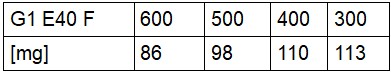
This is an important parameter. In the run-up, you should try some extrusion speeds. The higher the temperature the higher the extrusion speed. It is best to make tests in advance by simply creating a few plastic blobs with different extrusion speeds at different points on the print bed. Then weigh these blobs with a scale. You will find that these are easier to extrude at higher temperature. This depends on the machine and the print head. Determine a value at which the weight of the plastic samples has not fallen too much (about 10%) compared to a "slow" extrusion.
Time between extrusions
Another parameter is the time between extrusions. If the print head has been hot for a long time and nothing has been extruded the first "shot" can take place faster because there is enough hot plastic in the print head. This is important for deep structures. You can perform the first injection at high speed and then extrude it at a lower speed until end. Continuously extruding at high speed is pointless since the plastic can not be melted quickly enough. The drive wheels will spin on the filament.
If the print head is made entirely of metal (All metal hotend) the amount of plastic that can be produced is higher compared to a print head with teflon tubes.
Pressure bed temperature
It is recommended to work with a high (> 50 ° C) print bed temperature only for very complicated parts. At a high print bed temperature a complete cycle takes a very long time because the plastic must be sufficiently hard or cold to remove the mold. Heating also takes a very long time because silicone is not a good thermal conductor. Measure the temperature in the cavity as there is a significant temperature gradient between the print bed and the silicone mold.
Remedial measures for printing problems
Long parts not filled to the endIncrease temperature and extrusion speed. Position the print head just above the center. Print head as low as possible. If necessary heat the print bed.
Plastic compound is pressed from the silicone mold
Increase temperature reduce the extrusion rate. First fill areas of the mold which are deep or have undercuts.
Object is distorted when it is removed
Wait longer and possibly lower the temperature.
Object is very difficult to demold
Use softer silicone. Peel the object differently so that the undercuts in the demoulding direction are weaker.
Result also badly after many optimizations
Cavity, machine and plastic do not fit together.
Cycle time too long
Pour several similar objects into the silicone mold. Afterwards the objects can be printed one after the other and have more time to cool down. Ideally the 3D printer is always busy.
More options
- Multicolor printing with high precision
- Series production with a normal 3D printer
- Placing other materials in the cavity prior to injection, e.g. LED's incl. Cable.
There are certainly other possibilities. I look forward to exciting discussions. Enjoy the 3D-PIM technology.

If you have comments about this article or photos of further objects, you can send them to me gladly. Constructive criticism is always welcome :-).
Note: 3D-PIM also works with a 3D printing pen.