Stable flying and hovering drone
drones fly not intrinsically stable such as a parachute. This professional article provides an insight into the theory and practice of stable attitude and numerous possibilities for optimization of the flight model.
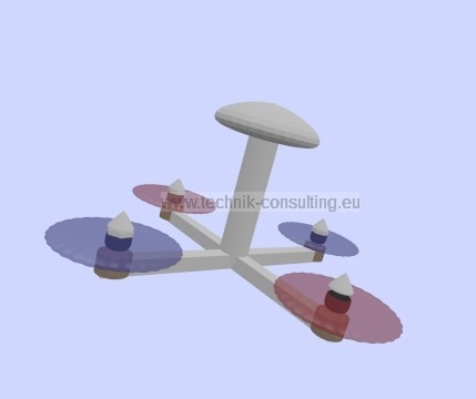
Foto: Dirk Brunner; Lizenz: CC BY SA 3.0
Causes of a stable flying and hovering
If you leave a sheet of paper flying there is an uncontrolled fall to the ground in most cases. However fold a paper airplane it is flying stable to the ground. This has to do with the centre of gravity and the wings. How deeper the center of gravity is the more stable the aircraft is flying but also lazy in changes of direction. Compare the flight characteristics of a parachute (low center of gravity) with those of a glider.drones are unstable
A drone is taking due to the following facts are not intrinsically stable (except for exceptions designed) and without electronics they can not stable fly:- high center of gravity
- low moment of inertia
- high wind sensitivity
sensors
The sensor system of a better drone provides information about acceleration, inclination, angular rate and pressure. With this information the electronics receive important information about the flight situation. An electronic control system tries to keep up with the engines the desired attitude. Thanks to ever-improving control technology it is thus possible to maintain extremely unstable models stable in the air.why is a drone stable hovering and flying?
How stable a drone is flying and hovering in the air is related to:- control electronics
- propulsion
- dimensions / configuration
- sensors
The model may have the best control electronics, propulsion and sensor technology and is not yet stable to fly. Think about the glaring errors in a drone if both propellers are interchanged, instead of being arranged diagonally. Such errors are unfortunately already happened and when the model is tried in hand to start to pass serious injury because the control electronics in this false assembly tries to stabilize the model.
For many applications it is very important to have a maximum stable drone. Imagine a movie on a strongly wabbly drone. The result is not usable if you do not use a good gimbal.
But why is a drone ultimately stable? Before we can answer this question the main components must be considered.
The propulsion system of a drone
Let's start with the propulsion.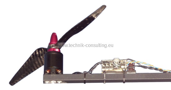
Foto: Dirk Brunner; Lizenz: CC BY SA 3.0
The propulsion includes the following components
- propeller
- motor
- motor controller (ESC)
For stability in the end is important how quickly and accurately the speed of the propeller can be changed. To change the rotation speed has to be supplied to the motor energy with an increase in speed and energy to be dissipated in a reduction of the speed (= brakes). The greater the performance of the controller or the motor has the faster the rotational speed can be changed.
The lower the moment of inertia of the system motor and propeller is the faster, when the same driving power, the changed speed.
The moment of inertia consists in a brushless external rotor composed of:
The energy of the rotary drive motion is:
f: revolution speed in 1/s
J_propulsion: moment of inertia propulsion (propeller + motor + mount)
Energy for driving the speed change
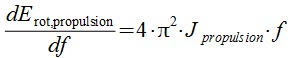
f: rpm in 1/s
df: change in rpm in 1/s
J_propulsion: moment of inertia propulsion (propeller + motor + mount)
This formula indicates how much energy (dE) is necessary to effect a change in rpm (df).
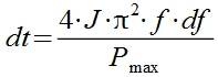
rpm change with maximum power
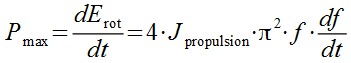
P_max: maximum power of the motor
f: rpm in 1/s
df: rpm change in 1/s
dt: time in s
J_propulsion: moment of inertia propulsion (propeller + motor + mount)
Time for change in speed for a given motor power
Time for rpm change at a given power with df = 0.1f. This corresponds approximately to the variable power for hovering.

control time of the propulsion system
10% corresponds to the typical speed range of a drone in hover.Warning: Depending on the controller's operation is in reality this time considerably larger. The theoretically given time represents the minimum. The motor controller are significantly faster compared to the mechanical components and are not considered further. Only the power of the motor controller (Electronic Speed Controller - ESC) must match to the motor.
In a medium-sized drone following values for the moments of inertia result:
- moment of inertia of a 11 "Carbon propeller: 5,7 E-05 kg*m2
- moment of inertia of a 2216 motor with mounting: 5,0 E-06 kg*m2
- total moment of inertia: 6,2 E-06 kg*m2
calculation of regulation time for the propulsion system
The time to change the rpm at 5000 1/min by 10% when using a 20A controller and a 3S battery (about 200 W) is with the 11 inches Propeller 8.5 ms. If an 8 inch propeller is used this time drops to 3.3 ms.This time is important and called t10%.
sensors of a drone
Sensors are required for the drone to detect the exact attitude. A better drone contains following sensors:- acceleration in 3 axes
- rate of rotation in 3 axes (gyro)
- air pressure (baro)
- magnetic in 3 axes (compass)
The following table lists the typical response times and sensitivities of the sensors in conjunction with a 12 bit AD-converter:
| sensor | response time | sensitivity |
|---|---|---|
| acceleration | 2 ms | 15 mV / (m/s2) ca. 0,07 m/(s2) |
| air pressure | 1 ms | 30 mV / kPa, ca. 3 m |
| rate of rotation | 1 ms | 10 mV /(°s) |
| magnetic | 1 ms | 1 mGs |
table - esponse times and sensitivities of the sensors
Compared to the response time of the propulsion system (about 5 ms) response times of the sensors are low.
closed loop frequency
The sensor data are provided to the control circuit or closed loop. The loop consists almost exclusively of software in a microcontroller. Today's systems achieve about 200 sensor evaluations per second (about 5 ms).This means that the propulsion system is compared to the sensor evaluation the slowest component.
The configuration
Drones can be constructed in different ways. If aerial photographs are made with a gimbal the center of gravity of such a drone is significantly below the propeller level. This results in a lazy drone.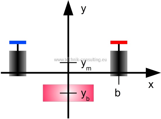
Foto: Dirk Brunner; Lizenz: CC BY SA 3.0
In this sentence a drone is shown schematically in the side view. The center of gravity of the drone located at y = 0. The center of gravity (COG) of an engine is on ym and the center of gravity of the batteries at yb. Other components such as mechanics and electronics are not considered. Compared with the engines or battery supply this a minor contribution to the total torque of the model. If necessary they can be added. However they can be added to the engine or battery.
moment of inertia of a drone
Thus the moment of inertia of a drone results to:m_m: mass propulsion system (propeller + motor + mount)
y_m: distance COG propulsion system to COG drone
y_b: distance COG battery to COG drone
The smaller the moment of inertia of the drone the easier it can be rotated.
This does not mean that a drone with a very high center of gravity can be rotated quickly. The moment of inertia is no longer the smallest in such a configuration. Such drone are merely particularly unstable.
The formula for the moment of inertia is comprehensible expect to the variable b. Because if b is very small although the total torque is small but at the same time the motors can then bring in only a small torque in the flight model.
angular acceleration drone
A better statement provides the angular acceleration. The bigger it is the faster the model can even put in rotation.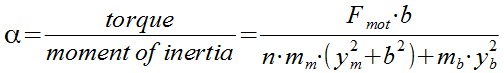
b: Distance motor axle to drone axle
n: number of motors
F_mot: Thrust force of a motor for rotation. If several motors are used simultaneously for the rotation multiply this value accordingly.
m_m: mass propulsion system (propeller + motor + mount)
y_m: distance COG propulsion system to COG drone
y_b: distance COG battery to COG drone
When the components (motor and battery) are exactly in the middle at the center of gravity (yp = yb = 0) the formula can be simplify:
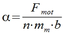
Ideal arrangement of the components
If a model is to be built which can be turned as quickly as possible in addition to light engines and propellers (at the same power) to strive for even the smallest possible distances from the central axis. Ideally the COG of the model is into the rotor level.Values of an agile drone are:
Fmot = 2 * 20 N (2 engines running simultaneously for rotation)
Mm = 0,1 kg
B = 0,2 m
This model requires from the rest about 0.1s to cover by an angle of 10°. For a complete rotation (half turn acceleration and a half turn brakes) is about 1s required.
Overturning of a drone at a too high COG
In very unfavorable center of gravity position and configuration a model can not be stabilized and falls over. This effect may occur on models with very high center of gravity or on models with very low center of gravity, which are rotated on the back (which the center of gravity is very high again). Ask here before a drone that a heavier camera in inverted flight. Incorrect interpretation of the model tilts to inevitably from a certain angle.
Foto: Dirk Brunner; Lizenz: CC BY SA 3.0
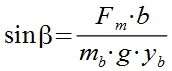
Animation drone overturning
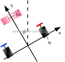
Foto: Dirk Brunner; Lizenz: CC BY SA 3.0
sketch stable drone overturning
Stability criterion overturning
Ideally the model is able to stabilize from any attitude again. In order to succeed must the torque produced by the propulsion system always be greater than gravitational torques. Aerodynamically acting torques during rapid flights are not considered here.This gives the following stability criterion
Torque drive > gravitational torque
Calculate maximum tilt angle
The angle from which the model can be tilted inevitably can be calculated with:it follows
This formula is valid only if the right hand side less than or equal 1. If greater than 1 the model can from any attitude stabilized.
b: distance motor axle to model axle
F_m: Thrust force of a propulsion system for rotation. If several motors are used simultaneously for the rotation multiply this value accordingly.
m_b: Mass above the center of gravity e.g. battery weight during inverted flight.
g: gravitational acceleration
y_b: distance battery COG to the model COG
From the angle beta the model itself begins inevitably to turn and can not be stabilized with the given pushing force. Can not increase the thrust or the model fly stable in the other location it crashes.
A stable drone
A stable model (= remains in the air) is composed ofTilt angle greater than about 60 °.
Control loop and propulsion system faster than t10°. --> t10% <t10°.
A very stable drone
A very stable and agile model has the following propertiesTorque motors > gravitational torque
(Model can straighten out any attitude)
Alpha huge i.e. strong drive propeller as close as possible in the center axis of the model and all the heavier components (eg battery) are disposed in the propeller plane.
Control loop and propulsion system significantly faster than t10 ° (t10% << t10 °).
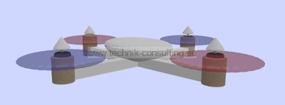
Foto: Dirk Brunner; Lizenz: CC BY SA 3.0
optimized drone
Appendix - Calculate inertia propeller
In order to determine the moment of inertia of a propeller that will gradually cut, weighed and measured.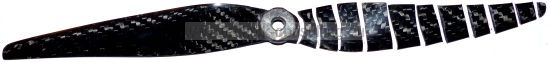
Foto: Dirk Brunner; Lizenz: CC BY SA 3.0
inertia propeller
Each piece of the propeller delivers according to the formula dJ = R2 * dm a contribution to the overall inertia. After summing up all propeller pieces the moment of inertia is known. In the illustrated 11-inch propeller from carbon the entire moment of inertia: 5,7 E-05 kg*m2. An 8 inch propeller has to compare a moment of inertia of 1,9 E-05 kg*m2.
Appendix - inertia motor and mounting
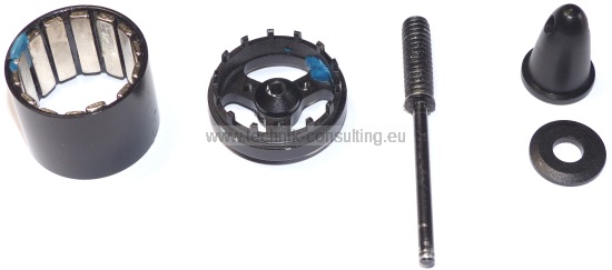
Foto: Dirk Brunner; Lizenz: CC BY SA 3.0
inertia motor and mounting
All moments of inertia of a typical 2216 motor incl. mounting together amount to 5,0 E-06 kg*m2 and therefore only 10% of the inertia of the 11 inch propeller.
Further analysis

If you need analyzes for other models I am at your disposal.